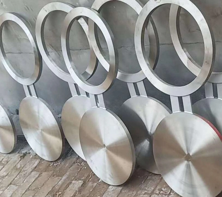
ASTM A182/A240 ASME B16.48 pipeline blind flange, 8-shaped blind flange, specification: 1/2 "-24", pressure rating: 150LB-2500LB; Suitable for liquid, particulate, and gas transportation pipelines, such as chemical, refining, boilers, power, offshore platforms, and other fields.
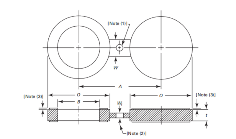
| Table 1 Dimensions of Class 150 Raised Face Figure-8 Blanks | |||||
| NPS | Inside Diameter, B mm | Outside Diameter, o mm | Centerline Dimension, A mm | Thickness, t mm | Web Width, W mm |
| ½ | 16 | 45 | 60 | 3.0 | 38 |
| ¾ | 21 | 54 | 70 | 3.0 | 38 |
| 1 | 27 | 64 | 80 | 3.0 | 38 |
| 1¼ | 42 | 73 | 90 | 6.4 | 38 |
| 1½ | 48 | 83 | 100 | 6.4 | 38 |
| 2 | 61 | 102 | 120 | 6.4 | 51 |
| 2½ | 73 | 107 | 140 | 6.4 | 51 |
| 3 | 89 | 133 | 150 | 6.4 | 64 |
| 3½ | 102 | 159 | 175 | 9.7 | 64 |
| 4 | 114 | 172 | 190 | 9.7 | 64 |
| 5 | 141 | 194 | 215 | 9.7 | 76 |
| 6 | 168 | 219 | 240 | 127 | 76 |
| 8 | 219 | 276 | 300 | 12.7 | 76 |
| 10 | 273 | 337 | 360 | 15.7 | 102 |
| 12 | 324 | 406 | 430 | 19.1 | 102 |
| 14 | 356 | 448 | 475 | 19.1 | 108 |
| 16 | 406 | 511 | 460 | 22.4 | 108 |
| 18 | 457 | 546 | 580 | 25.4 | 114 |
| 20 | 508 | 603 | 635 | 28.4 | 121 |
| 24 | 610 | 714 | 750 | 31.8 | 140 |
GENERAL NOTE: Dimensions are in millimeters. for inch dimensions, refer to corresponding Table A-1 in Nonmandatory Appendix A.
NOTES:
(1) Hole size (where required due to bolt spacing) shall be the same as the flange bolt hole and located such that it will not interfere with bolting between two flanges.
(2) The thickness of the web (or tie bar) dimension, W, shall be as determined by para. 3.1.
(3) Referto para. 3.3.1.
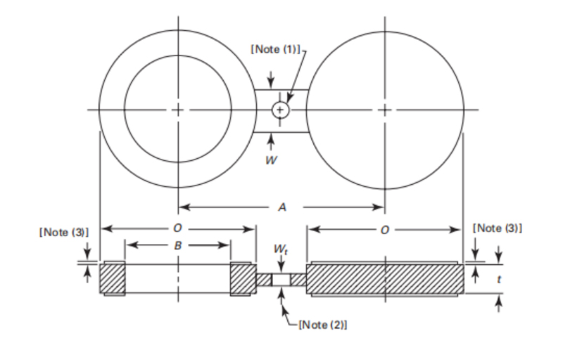
| Table 2 Dimensions of Class 300 Raised Face Figure-8 Blanks | |||||
| NPS | Inside Diameter, B, mm | Outside Diameter, O, mm | Centerline Dimension, A, mm | Thickness, t, mm | Web Width, W, mm |
| ½ | 16 | 51 | 65 | 6.4 | 38 |
| ¾ | 21 | 64 | 80 | 6.4 | 38 |
| 1 | 27 | 70 | 90 | 6.4 | 38 |
| 1¼ | 42 | 79 | 100 | 6.4 | 38 |
| 1½ | 48 | 92 | 115 | 6.4 | 38 |
| 2 | 61 | 108 | 125 | 9.7 | 51 |
| 2½ | 73 | 127 | 150 | 9.7 | 51 |
| 3 | 89 | 146 | 170 | 9.7 | 64 |
| 3½ | 102 | 162 | 185 | 12.7 | 64 |
| 4 | 114 | 178 | 200 | 12.7 | 64 |
| 5 | 141 | 213 | 235 | 15.7 | 76 |
| 6 | 168 | 248 | 270 | 15.7 | 76 |
| 8 | 219 | 305 | 330 | 22.4 | 76 |
| 10 | 273 | 359 | 385 | 25.4 | 102 |
| 12 | 324 | 419 | 450 | 28.4 | 102 |
| 14 | 356 | 483 | 515 | 31.8 | 108 |
| 16 | 406 | 536 | 570 | 38.1 | 108 |
| 18 | 457 | 594 | 630 | 41.1 | 114 |
| 20 | 508 | 651 | 685 | 44.5 | 121 |
| 24 | 610 | 772 | 810 | 50.8 | 140 |
GENERAL NOTE: Dimensions are in millimeters. for inch dimensions, refer to corresponding Table A-2 in Nonmandatory Appendix A.
NOTES:
(1) Hole size (where required due to bolt spacing) shall be the same as the flange bolt hole and located such that it will not interfere with bolting between two flanges.
(2) The thickness of the web (or tie bar) dimension, W, shall be as determined by para. 3.1.
(3) Refer to para. 3.3.1.
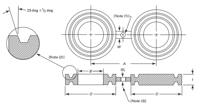
| Table 7 Dimensions of Class 1500 Female Ring-Joint Facing Figure-8 Blanks | |||||
| NPS | Inside Diameter, B. mm | Outside Diameter, O. mm | Centerline Dimension, A, mm | Thickness, t, mm | Web Width, W, mm |
| 1 | 34 | 64 | 80 | 19.1 | 51 |
| 1¼ | 42 | 73 | 90 | 19.1 | 51 |
| 1½ | 48 | 83 | 100 | 19.1 | 57 |
| 2 | 61 | 102 | 120 | 19.1 | 57 |
| 2½ | 73 | 121 | 140 | 22.4 | 57 |
| 3 | 89 | 133 | 150 | 22.4 | 57 |
| 3½ | 102 | 154 | 175 | 22.4 | 64 |
| 4 | 114 | 172 | 190 | 224 | 64 |
| 5 | 141 | 194 | 215 | 25.4 | 70 |
| 6 | 168 | 219 | 240 | 25.4 | 83 |
| 8 | 219 | 273 | 300 | 28.4 | 95 |
| 10 | 273 | 33 | 360 | 31.8 | 102 |
| 12 | 324 | 406 | 430 | 35.1 | 121 |
| 14 | 356 | 426 | 475 | 35.1 | 127 |
| 16 | 406 | 483 | 540 | 38.1 | 127 |
| 18 | 457 | 546 | 580 | 41.1 | 127 |
| 20 | 508 | 597 | 635 | 41.1 | 127 |
| 24 | 610 | 711 | 750 | 47.8 | 152 |
GENERAL NOTE: Dimensions are in millimeters. for inch dimensions, refer to corresponding Table A-7 in Nonmandatory Appendix A.
NOTES:
(1) Hole size (where required due to bolt spacing) shall be the same as the flange bolt hole and located such that it will not interfere with bolting between two flanges.
(2) Female ringjoint groove dimensions shall be in accordance with ASME B16.5.
(3) The thickness of the web (or tie bar) dimension, W, shall be as determined by para. 3.1.
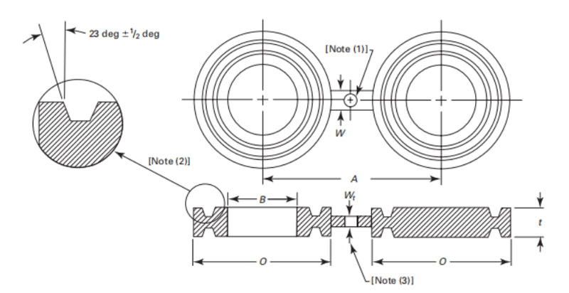
| Table 8 Dimensions of Class 300 Female Ring-Joint Facing Figure-8 Blanks | |||||
| NPS | Inside Diameter, B, mm | Outside Diameter, 0, mm | Centerline Dimension, A, mm | Thickness, t, mm | Web width, w, mm |
| ½ | 21 | 51 | 65 | 15.7 | 38 |
| ¾ | 27 | 64 | 80 | 19.1 | 45 |
| 1 | 34 | 70 | 90 | 19.1 | 51 |
| 1¼ | 42 | 79 | 100 | 22.4 | 51 |
| 1½ | 48 | 90 | 115 | 22.4 | 57 |
| 2 | 61 | 108 | 125 | 25.4 | 57 |
| 2½ | 73 | 127 | 150 | 28.4 | 57 |
| 3 | 89 | 146 | 170 | 28.4 | 57 |
| 3½ | 102 | 159 | 185 | 28.4 | 64 |
| 4 | 114 | 175 | 200 | 31.8 | 64 |
| 5 | 141 | 210 | 235 | 35.1 | 70 |
| 6 | 168 | 241 | 270 | 35.1 | 83 |
| 8 | 219 | 302 | 330 | 41.1 | 95 |
| 10 | 273 | 356 | 385 | 44.5 | 102 |
| 12 | 324 | 413 | 450 | 50.8 | 121 |
| 14 | 356 | 457 | 515 | 53.8 | 127 |
| 16 | 406 | 508 | 570 | 57.2 | 127 |
| 18 | 457 | 575 | 630 | 60.5 | 127 |
| 20 | 508 | 635 | 685 | 69.9 | 127 |
| 24 | 610 | 749 | 810 | 79.2 | 152 |
GENERAL NOTE: Dimensions are in millimeters. For inch dimensions, refer to corresponding Table A-8 in Nonmandatory Appendix A.
NOTES:
(1) Hole size (where required due to bolt spacing) shall be the same as the flange bolt hole and located such that it will not interfere with bolting between two flanges.
(2) Female ring-joint groove dimensions shall be in accordance with ASME B16.5.
(3) The thickness of the web (or tie bar) dimension, w, shall be as determined by para. 3.1
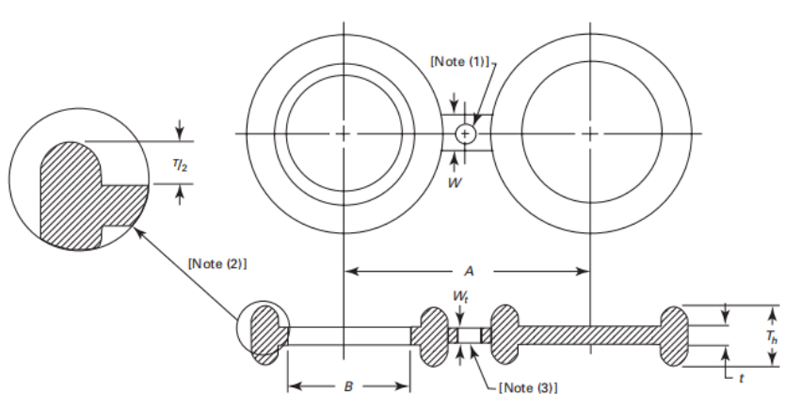
| Table 13 Dimensions of Class 150 Male Oval Ring-Joint Facing Figure-8 Blanks | ||||
| NPS | Inside Diameter, B, mm | Centerline Dimension, A. mm | Thickness, t, mm | Web Width, W, mm |
| 1 | 34 | 80 | 6.4 | 51 |
| 1¼ | 42 | 90 | 6.4 | 51 |
| 1½ | 48 | 100 | 6.4 | 57 |
| 2 | 61 | 120 | 6.4 | 57 |
| 2½ | 73 | 140 | 9.7 | 57 |
| 3 | 89 | 150 | 9.7 | 57 |
| 3½ | 102 | 175 | 9.7 | 64 |
| 4 | 114 | 190 | 9.7 | 64 |
| 5 | 141 | 215 | 12.7 | 76 |
| 6 | 168 | 240 | 12.7 | 83 |
| 8 | 219 | 300 | 15.7 | 95 |
| 10 | 273 | 362 | 19.1 | 102 |
| 12 | 324 | 432 | 22.4 | 121 |
| 14 | 356 | 476 | 22.4 | 127 |
| 16 | 406 | 540 | 25.4 | 127 |
| 18 | 457 | 578 | 28.4 | 127 |
| 20 | 508 | 635 | 28.4 | 127 |
| 24 | 610 | 749 | 35.1 | 152 |
GENERAL NOTE: Dimensions are in millimeters. For inch dimensions, refer to corresponding Table A-13in Nonmandatory Appendix A.
NOTES:
(1) Hole size (where required due to bolt spacing) shall be the same as the flange bolt hole and located such that it will not interfere with bolting between two flanges.
(2) Oval ring*joint dimensions shall be in accordance with ASME B16.20, except 7h = T+ t, where Tis the ring height specified in ASME B16.20.
(3) The thickness of the web (or tie bar dimension, W, shall be as determined by para. 3.1.
KIDY is a service-oriented enterprise with a complete range of steel grades; Conventional steel grades F304/304L, F321, F316/316L, and other material specifications are available for long-term flange blanks for quick delivery. The packaging is in export wooden boxes, and special size requirements can be customized.

Customer Satisfaction Is Our Honor. Feel free to enquiry us any questions of pipeline materials.


