


In pipeline systems, welded pipe fittings are pressure pipeline components used to change the direction or diameter of pipelines, branch pipelines, and achieve special connection functions in production equipment such as petrochemical and power plants. They are fittings connected to pipes through welding, especially suitable for long pipelines and pipelines that do not require frequent disassembly. Due to changes in the flow direction and flow area of the medium at its installation location, its internal and external stress situations are relatively complex. Therefore, the quality level of the pipe fittings directly affects the safe and stable operation of the entire pipeline system. They have multiple product types to choose from, such as 90 ° elbows, 45 ° elbows, tees, tees, caps, concentric reducers, eccentric reducers, and flanged short joints. The product standards DIN2605, DIN2615, DIN2616, DIN2617, EN10253 are mainly applicable to high-pressure pipelines, equipment with precise dimensions, and various other high-pressure fields that require high pressure resistance, such as petrochemicals, medicine and health, electricity, aerospace, fire protection, metallurgy, shipbuilding, gas, nuclear power, and environmental protection.

Nominal size DN | Pipe outside diameter, dat) | Type | Wall thickness,s. for series | Maximum pressure factor, as a percentage, for series | r | b | e | ||||||||
| 1 | 22) | 3 | 4 | 5 | 1 | 2 | 3 | 4 | 5 | ||||||
| 15 | 21.3 | 2 3 5 | 1.6 | - | 2.0 | 3.2 | 4.0 | 53 74 85 | - | 54 75 85 | 57 75 85 | 59 76 85 | 17.5 28.0 42.5 | 28 38 53 | 7 12 18 |
| 20 | 26.9 | 2 3 5 | 1.6 | - | 2.3 | 3.2 | 4.0 | 59 67 86 | - | 60 68 86 | 61 68 86 | 62 69 86 | 25.0 29.0 57.5 | 39 43 71 | 10 12 24 |
| 25 | 33.7 | 2 3 5 | 2.0 | - | 2.6 | 3.2 | 4.0 | 52 70 86 | - | 53 70 86 | 54 70 86 | 55 71 86 | 25.0 38.0 72.5 | 42 56 90 | 10 16 30 |
| 32 | 42.4 | 2 3 5 | 2.0 | - | 2.6 | 3.6 | 4.0 | 52 70 86 | - | 52 70 86 | 54 71 87 | 54 71 87 | 32.0 48.0 92.5 | 53 69 114 | 13 20 38 |
| 40 | 48.3 | 2 3 5 | 2.0 | - | 2.6 | 4.0 | 5.0 | 51 72 87 | - | 52 72 87 | 53 73 87 | 54 73 87 | 38.0 57.0 107.5 | 62 82 132 | 16 24 45 |
| 50 | 60.3 | 2 3 5 10 20 | 2.0 | - | 2.9 | 4.5 | 5.6 | 56 74 87 92 96 | - | 56 74 87 93 96 | 57 75 87 93 96 | 58 75 87 93 96 | 51 76 135 254 508 | 81 106 165 284 538 | 21 32 56 105 210 |
| 65 | 76.1 | 2 3 5 10 20 | 2.3 | - | 2.9 | 5.0 | 7.1 | 55 74 87 92 96 | - | 55 74 87 92 96 | 56 75 87 92 96 | 57 75 87 93 96 | 63 95 175 318 635 | 102 133 213 356 673 | 26 39 73 132 263 |
| 80 | 88.9 | 2 3 5 10 20 | 2.3 | - | 3.2 | 5.6 | 8.0 | 57 75 87 93 96 | - | 57 75 87 93 96 | 58 75 87 93 96 | 59 76 88 93 96 | 76 114 205 381 762 | 121 159 250 425 806 | 32 47 85 158 316 |
| 100 | 114.3 | 2 3 5 10 20 | 2.6 | - | 3.6 | 6.3 | 8.8 | 60 76 88 93 96 | - | 60 76 88 93 96 | 61 76 88 93 96 | 61 76 88 93 96 | 102 152 270 508 1016 | 159 210 327 565 1073 | 42 63 112 210 421 |
| 125 | 139.7 | 2 3 5 10 20 | 2.6 | - | 4.0 | 6.3 | 10.0 | 61 77 88 93 97 | - | 61 77 88 93 97 | 61 77 88 93 97 | 62 77 88 93 97 | 127 190 330 635 1270 | 197 260 400 705 1340 | 53 79 137 263 526 |
| 150 | 168.3 | 2 3 5 10 20 | 2.8 | 4.0 | 4.5 | 7.1 | 11.0 | 60 77 87 93 97 | 61 77 87 93 97 | 61 77 87 93 97 | 61 77 87 93 97 | 61 77 88 93 97 | 152 229 390 762 1524 | 237 313 474 846 1608 | 63 95 162 318 631 |
1) The pipe outside diameters given have been taken from series 1 in ISO 4200.
2) The wall thicknesses specified for series 2, for nominal sizes up to DN 1000, are in accordance with the normal wall thickness series given in DIN 2458.
A dash in a box indicates a size that has not been standardized.
Nominal width DN1 | Diameter d1 | Wall thickness S1 Raihe | Nominal width DN2 | Diameter d2 | Wall thickness S2 Raihe | a | b | Permissible degree of utilization as % of wall thickness一Series | ||||||||||||
| 1 | 2 | 3 | 4 | 5 | 1 | 2 | 3 | 4 | 5 | 1 | 2 | 3 | 4 | 5 | ||||||
| 15 | 21.3 | 1.6 | - | 2.0 | 3.2 | 4.0 | 15 | 21.3 | 1.6 | - | 2.0 | 3.2 | 4.0 | 25 | 25 | 52 | - | 55 | 62 | 66 |
| 10 | 17.2 | 1.6 | - | 1.8 | 2.9 | - | 25 | 60 | - | 59 | 73 | - | ||||||||
| 20 | 26.9 | 1.6 | - | 2.3 | 3.2 | 4.0 | 20 | 26.9 | 1.8 | - | 2.3 | 3.2 | 4.0 | 29 | 29 | 49 | - | 54 | 59 | 62 |
| 15 | 21.3 | 1.6 | - | 2.0 | 3.2 | 4.0 | 29 | 57 | - | 57 | 69 | 73 | ||||||||
| 10 | 17.2 | 1.6 | - | 1.8 | 2.9 | - | 29 | 65 | - | 61 | 73 | - | ||||||||
| 25 | 33.7 | 2.0 | - | 2.6 | 3.2 | 4.0 | 25 | 33.7 | 2.0 | - | 2.6 | 3.2 | 4.0 | 38 | 38 | 49 | - | 52 | 55 | 59 |
| 20 | 26.9 | 1.6 | - | 2.3 | 3.2 | 4.0 | 38 | 49 | - | 56 | 64 | 69 | ||||||||
| 15 | 21.3 | 1.6 | - | 2.0 | 3.2 | 4.0 | 38 | 57 | - | 59 | 74 | 79 | ||||||||
| 32 | 42.4 | 2.0 | - | 2.6 | 3.6 | 4.0 | 32 | 42.4 | 2.0 | - | 2.6 | 3.6 | 4.0 | 48 | 48 | 46 | - | 49 | 54 | 55 |
| 25 | 33.7 | 2.0 | - | 2.6 | 3.2 | 4.0 | 48 | 53 | - | 57 | 58 | 65 | ||||||||
| 20 | 26.9 | 1.6 | - | 2.3 | 3.2 | 4.0 | 48 | 53 | - | 61 | 66 | 74 | ||||||||
| 15 | 21.3 | 1.6 | - | 2.0 | 3.2 | 4.0 | 48 | 60 | - | 63 | 76 | 84 | ||||||||
| 40 | 48.3 | 2.0 | - | 2.6 | 4.0 | 5.0 | 40 | 48.3 | 2.0 | - | 2.6 | 4.0 | 5.0 | 57 | 57 | 44 | - | 47 | 53 | 57 |
| 32 | 42.4 | 2.0 | - | 2.6 | 3.6 | 4.0 | 57 | 48 | - | 52 | 54 | 59 | ||||||||
| 25 | 33.7 | 2.0 | - | 2.6 | 3.2 | 4.0 | 57 | 55 | - | 60 | 58 | 62 | ||||||||
| 20 | 26.9 | 1.6 | - | 2.3 | 3.2 | 4.0 | 57 | 55 | - | 63 | 67 | 71 | ||||||||
| 50 | 60.3 | 2.0 | - | 2.9 | 4.5 | 5.6 | 50 | 60.3 | 2.0 | - | 2.9 | 4.5 | 5.6 | 64 | 64 | 41 | - | 46 | 52 | 55 |
| 40 | 48.3 | 2.0 | - | 2.6 | 4.0 | 5.0 | 60 | 48 | - | 49 | 55 | 59 | ||||||||
| 32 | 42.4 | 2.0 | - | 2.6 | 3.6 | 4.0 | 57 | 52 | - | 64 | 56 | 56 | ||||||||
| 25 | 33.7 | 2.0 | - | 2.8 | 3.2 | 4.0 | 51 | 59 | - | 61 | 60 | 64 | ||||||||
| 20 | 26.9 | 1.6 | - | 2.3 | 3.2 | 4.0 | 44 | 58 | - | 64 | 68 | 72 | ||||||||
Nominal width DN1 | Diameter d1 | Wall thickness S1 Raihe | Nominal width DN2 | Diameter d2 | Wall thickness S2 Raihe | a | b | Permissible degree of utilization as % of wall thickness一Series | ||||||||||||
| 1 | 2 | 3 | 4 | 5 | 1 | 2 | 3 | 4 | 5 | 1 | 2 | 3 | 4 | 5 | ||||||
| 65 | 76.1 | 2.3 | - | 2.9 | 5.0 | 7.1 | 65 | 76.1 | 2.3 | - | 2.9 | 5.0 | 7.1 | 76 | 76 | 40 | - | 43 | 50 | 55 |
| 50 | 60.3 | 2.0 | - | 2.9 | 4.5 | 5.6 | 70 | 42 | - | 50 | 54 | 55 | ||||||||
| 40 | 48.3 | 2.0 | - | 2.6 | 4.0 | 5.0 | 67 | 49 | - | 53 | 58 | 59 | ||||||||
| 32 | 42.4 | 2.0 | - | 2.6 | 3.6 | 4.0 | 64 | 53 | - | 57 | 59 | 57 | ||||||||
| 25 | 33.7 | 2.0 | - | 2.6 | 3.2 | 4.0 | 57 | 60 | - | 65 | 63 | 65 | ||||||||
| 80 | 88.9 | 2.3 | - | 3.2 | 5.6 | 8.0 | 80 | 88.9 | 2.3 | - | 3.2 | 5.6 | 8.0 | 86 | 86 | 38 | - | 42 | 50 | 55 |
| 65 | 76.1 | 2.3 | - | 2.9 | 5.0 | 7.1 | 83 | 42 | - | 44 | 51 | 56 | ||||||||
| 50 | 60.3 | 2.0 | - | 2.9 | 4.5 | 5.6 | 76 | 45 | - | 51 | 55 | 56 | ||||||||
| 40 | 48.3 | 2.0 | - | 2.6 | 4.0 | 5.0 | 73 | 51 | - | 54 | 59 | 60 | ||||||||
| 32 | 42.4 | 2.0 | - | 2.6 | 3.6 | 4.0 | 70 | 55 | - | 58 | 60 | 59 | ||||||||
| 100 | 114.3 | 2.6 | - | 3.6 | 6.3 | 8.8 | 100 | 114.3 | 2.6 | - | 3.6 | 6.3 | 8.8 | 105 | 105 | 37 | - | 40 | 48 | 52 |
| 80 | 88.9 | 2.3 | - | 3.2 | 5.6 | 8.0 | 98 | 40 | - | 44 | 52 | 58 | ||||||||
| 65 | 76.1 | 2.3 | - | 2.9 | 5.0 | 7.1 | 95 | 44 | - | 46 | 53 | 59 | ||||||||
| 50 | 60.3 | 2.0 | - | 2.9 | 4.5 | 5.6 | 89 | 46 | - | 53 | 58 | 60 | ||||||||
| 40 | 48.3 | 2.0 | - | 2.6 | 4.0 | 5.0 | 86 | 53 | - | 56 | 61 | 64 | ||||||||
| 125 | 139.7 | 2.6 | - | 4.0 | 6.3 | 10.0 | 125 | 139.7 | 2.6 | - | 4.0 | 6.3 | 10 | 124 | 124 | 34 | - | 39 | 45 | 51 |
| 100 | 114.3 | 2.6 | - | 3.6 | 6.3 | 8.8 | 117 | 39 | - | 42 | 52 | 54 | ||||||||
| 80 | 88.9 | 2.3 | - | 3.2 | 5.6 | 8.0 | 111 | 42 | - | 46 | 56 | 59 | ||||||||
| 65 | 76.1 | 2.3 | - | 2.9 | 5.0 | 7.1 | 108 | 46 | - | 47 | 57 | 61 | ||||||||
| 50 | 60.3 | 2.0 | - | 2.9 | 4.5 | 5.6 | 105 | 49 | - | 54 | 61 | 61 | ||||||||
Nominal width DN1 | Diameter d1 | Wall thickness S1 Raihe | Nominal width DN2 | Diameter d2 | Wall thickness S2 Raihe | a | b | Permissible degree of utilization as % of wall thickness一Series | ||||||||||||
| 1 | 2 | 3 | 4 | 5 | 1 | 2 | 3 | 4 | 5 | 1 | 2 | 3 | 4 | 5 | ||||||
| 150 | 168.3 | 2.6 | 4.0 | 4.5 | 7.1 | 11.0 | 150 | 168.3 | 2.6 | 4.0 | 4.5 | 7.1 | 11.0 | 143 | 143 | 32 | 37 | 38 | 44 | 50 |
| 125 | 139.7 | 2.6 | - | 4.0 | 6.3 | 10.0 | 137 | 36 | - | 40 | 46 | 53 | ||||||||
| 100 | 114.3 | 2.6 | - | 3.6 | 6.3 | 8.8 | 130 | 41 | - | 43 | 52 | 56 | ||||||||
| 80 | 88.9 | 2.3 | - | 3.2 | 5.6 | 8.0 | 124 | 44 | - | 47 | 57 | 61 | ||||||||
| 65 | 76.1 | 2.3 | - | 2.9 | 5.0 | 7.1 | 121 | 49 | - | 49 | 58 | 62 | ||||||||
| 200 | 219.1 | 2.9 | 4.57 | 6.3 | 8.0 | 12.5 | 200 | 219.1 | 2.9 | 4.5 | 6.3 | 8.0 | 12.5 | 178 | 178 | 30 | 35 | 39 | 42 | 48 |
| 150 | 168.3 | 2.6 | 4.0 | 4.5 | 7.1 | 11.0 | 168 | 34 | 39 | 41 | 46 | 53 | ||||||||
| 125 | 139.7 | 2.6 | - | 4.0 | 6.3 | 10.0 | 162 | 38 | - | 40 | 48 | 56 | ||||||||
| 100 | 114.3 | 2.6 | - | 3.6 | 6.3 | 8.8 | 156 | 43 | - | 44 | 55 | 58 | ||||||||
| 80 | 88.9 | 2.3 | - | 3.2 | 5.6 | 8.0 | 152 | 46 | - | 48 | 59 | 63 | ||||||||
| 250 | 273.0 | 2.9 | 5.0 | 6.3 | 8.8 | 14.2 | 250 | 273.0 | 2.9 | 5.0 | 6.3 | 8.8 | 14.2 | 216 | 216 | 28 | 34 | 37 | 41 | 47 |
| 200 | 219.1 | 2.9 | 4.5 | 6.3 | 8.0 | 12.5 | 203 | 32 | 37 | 42 | 44 | 50 | ||||||||
| 150 | 168.3 | 2.6 | 4.0 | 4.5 | 7.1 | 11.0 | 194 | 36 | 40 | 41 | 48 | 54 | ||||||||
| 125 | 139.7 | 2.6 | - | 4.0 | 6.3 | 10.0 | 191 | 40 | - | 43 | 51 | 57 | ||||||||
| 100 | 114.3 | 2.6 | - | 3.6 | 6.3 | 8.8 | 184 | 45 | - | 47 | 56 | 60 | ||||||||
| 300 | 323.9 | 2.9 | 5.6 | 7.1 | 10.0 | 16.0 | 300 | 323.9 | 2.9 | 5.6 | 7.1 | 10.0 | 16.0 | 254 | 254 | 26 | 33 | 36 | 40 | 46 |
| 250 | 273.0 | 2.9 | 5.0 | 6.3 | 8.8 | 14.2 | 241 | 30 | 34 | 37 | 41 | 48 | ||||||||
| 200 | 219.1 | 2.9 | 4.5 | 6.3 | 8.0 | 12.5 | 229 | 34 | 37 | 43 | 45 | 51 | ||||||||
| 150 | 168.3 | 2.6 | 4.0 | 4.5 | 7.1 | 11.0 | 219 | 37 | 41 | 42 | 49 | 55 | ||||||||
| 125 | 139.7 | 2.6 | - | 4.0 | 6.3 | 10.0 | 216 | 42 | - | 45 | 52 | 59 | ||||||||

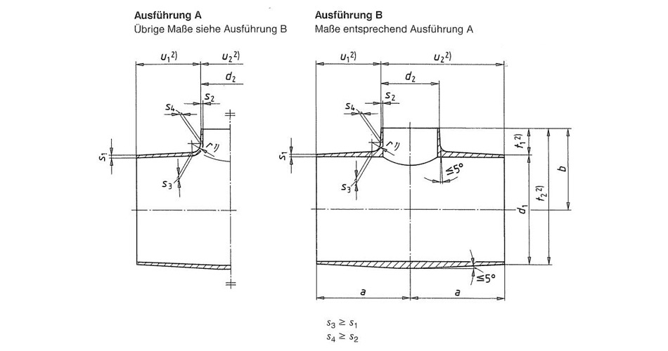
Nominal width DN1 | Diameter d1 | Wall thickness S1, for series | α max. | Nominal width DN2 | Diameter d2 | Wall thickness S2, for series | l1 | Wall thickness S3, for series | ||||||||||||
| 1 | 2 | 3 | 4 | 5 | 1 | 2 | 3 | 4 | 5 | 1 | 2 | 3 | 4 | 5 | ||||||
| 15 | 21.3 | 1.6 | - | 2.0 | 3.2 | 4.0 | 6 | 10 | 17.2 | 1.6 | - | 1.8 | 2.9 | - | 38 | 1.6 | - | 2.0 | 3.2 | - |
| 20 | 26.9 | 1.6 | - | 2.3 | 3.2 | 4.0 | 8 | 15 | 21.3 | 1.6 | - | 2.0 | 3.2 | 4.0 | 38 | 1.6 | - | 2.3 | 3.2 | 4.0 |
| 12 | 10 | 17.2 | 1.6 | - | 1.8 | 2.9 | - | 1.6 | - | 2.3 | 3.2 | - | ||||||||
| 25 | 33.7 | 2.0 | - | 2.6 | 3.2 | 4.0 | 7 | 20 | 26.9 | 1.6 | - | 2.3 | 3.2 | 4.0 | 50 | 2.0 | - | 2.6 | 3.2 | 4.0 |
| 12 | 15 | 21.3 | 1.6 | - | 2.0 | 3.2 | 4.0 | |||||||||||||
| 32 | 42.4 | 2.0 | - | 2.6 | 3.6 | 4.0 | 9 | 25 | 33.7 | 2.0 | - | 2.6 | 3.2 | 4.0 | 50 | 2.0 | - | 2.6 | 3.6 | 4.0 |
| 15 | 20 | 26..9 | 1.6 | - | 2.3 | 3.2 | 4.0 | |||||||||||||
| 19 | 15 | 21.3 | 1.6 | - | 2.0 | 3.2 | 4.0 | |||||||||||||
| 40 | 48.3 | 2.0 | - | 2.6 | 4.0 | 5.0 | 6 | 32 | 42.4 | 2.0 | - | 2.6 | 3.6 | 4.0 | 64 | 2.0 | - | 2.6 | 4.0 | 5.0 |
| 10 | 25 | 33.7 | 2.0 | - | 2.6 | 3.2 | 4.0 | |||||||||||||
| 16 | 20 | 26.9 | 1.6 | - | 2.3 | 3.2 | 4.0 | |||||||||||||
| 50 | 60.3 | 2.0 | - | 2.9 | 4.5 | 5.6 | 7 | 40 | 48.3 | 2.0 | - | 2.6 | 4.0 | 5.0 | 76 | 2.0 | - | 2.9 | 4.5 | 5.6 |
| 11 | 32 | 42.4 | 2.0 | - | 2.6 | 3.6 | 4.0 | |||||||||||||
| 16 | 25 | 33.7 | 2.0 | - | 2.6 | 3.2 | 4.0 | |||||||||||||
| 21 | 20 | 26.9 | 1.6 | - | 2.3 | 3.2 | 4.0 | |||||||||||||
| 65 | 76.1 | 2.3 | - | 2.9 | 5.0 | 7.1 | 9 | 50 | 60.3 | 2.0 | - | 2.9 | 4.5 | 5.6 | 90 | 2.3 | - | 2.9 | 5.0 | 7.1 |
| 15 | 40 | 48.3 | 2.0 | - | 2.6 | 4.0 | 5.0 | |||||||||||||
| 18 | 32 | 42.4 | 2.0 | - | 2.6 | 3.6 | 4.0 | |||||||||||||
| 23 | 25 | 33.7 | 2.0 | - | 2.6 | 3.2 | 4.0 | |||||||||||||
| 80 | 88.9 | 2.3 | - | 3.2 | 5.6 | 8.0 | 7 | 65 | 76.1 | 2.3 | - | 2.9 | 5.0 | 7.1 | 90 | 2.3 | - | 3.2 | 5.6 | 8.0 |
| 16 | 50 | 60.3 | 2.0 | - | 2.9 | 4.5 | 5.6 | |||||||||||||
| 22 | 40 | 48.3 | 2.0 | - | 2.6 | 4.0 | 5.0 | |||||||||||||
| 26 | 32 | 42.4 | 2.0 | - | 2.6 | 3.6 | 4.0 | |||||||||||||
Nominal width DN1 | Diameter d1 | Wall thickness S1, for series | α max. | Nominal width DN2 | Diameter d2 | Wall thickness S2, for series | l1 | Wall thickness S3, for series | ||||||||||||
| 1 | 2 | 3 | 4 | 5 | 1 | 2 | 3 | 4 | 5 | 1 | 2 | 3 | 4 | 5 | ||||||
| 100 | 114.3 | 2.6 | - | 3.6 | 6.3 | 8.8 | 13 | 80 | 88.9 | 2.3 | - | 3.2 | 5.6 | 8.0 | 100 | 2.6 | - | 3.6 | 6.3 | 8.8 |
| 18 | 65 | 76.1 | 2.3 | - | 2.9 | 5.0 | 7.1 | |||||||||||||
| 26 | 50 | 60.3 | 2.0 | - | 2.9 | 4.5 | 5.6 | |||||||||||||
| 31 | 40 | 48.3 | 2.0 | - | 2.6 | 4.0 | 5.0 | |||||||||||||
| 125 | 139.7 | 2.6 | - | 4.0 | 6.3 | 10.0 | 10 | 100 | 114.3 | 2.6 | - | 3.6 | 6.3 | 8.8 | 127 | 2.6 | - | 4.0 | 6.3 | 10.0 |
| 20 | 80 | 88.9 | 2.3 | - | 3.2 | 5.6 | 8.0 | |||||||||||||
| 25 | 65 | 76.1 | 2.3 | - | 2.9 | 5.0 | 7.1 | |||||||||||||
| 30 | 50 | 60.3 | 2.0 | - | 2.9 | 4.5 | 5.6 | |||||||||||||
| 150 | 168.3 | 2.6 | 4.0 | 4.5 | 7.1 | 11.0 | 9 | 125 | 139.7 | 2.6 | 4.0 | 4.0 | 6.3 | 10.0 | 140 | 2.6 | 4.0 | 4.5 | 7.1 | 11.0 |
| 19 | 100 | 114.3 | 2.6 | 3.6 | 3.6 | 6.3 | 8.8 | |||||||||||||
| 27 | 80 | 88.9 | 2.3 | 3.2 | 3.2 | 5.6 | 8.0 | |||||||||||||
| 31 | 65 | 76.1 | 2.3 | 2.9 | 2.9 | 5.0 | 7.1 | |||||||||||||
| 200 | 219.1 | 2.9 | 4.5 | 6.3 | 8.0 | 12.5 | 18 | 150 | 168.3 | 2.6 | 4.0 | 4.5 | 7.1 | 11.0 | 152 | 2.9 | 4.5 | 6.3 | 8.0 | 12.5 |
| 27 | 125 | 139.7 | 2.6 | 4.0 | 4.0 | 6.3 | 10.0 | |||||||||||||
| 33 | 100 | 114.3 | 2.6 | 3.6 | 3.6 | 6.3 | 8.8 | |||||||||||||
| 39 | 80 | 88.9 | 2.3 | 3.2 | 3.2 | 5.6 | 8.0 | |||||||||||||
| 250 | 273.0 | 2.9 | 5.0 | 6.3 | 8.8 | 14.2 | 16 | 200 | 219.1 | 2.9 | 4.5 | 6.3 | 8.0 | 12.5 | 178 | 2.9 | 5.0 | 6.3 | 8.8 | 14.2 |
| 30 | 150 | 168.3 | 2.6 | 4.0 | 4.5 | 7.1 | 11.0 | |||||||||||||
| 36 | 125 | 139.7 | 2.6 | 4.0 | 4.0 | 6.3 | 10.0 | 3.0 | 5.0 | 6.3 | 8.8 | 14.2 | ||||||||
| 40 | 100 | 114.3 | 2.6 | 3.6 | 3.6 | 6.3 | 8.8 | 3.1 | 5.0 | 6.3 | 8.8 | 14.2 | ||||||||
| 300 | 323.9 | 2.9 | 5.6 | 7.1 | 10.0 | 16.0 | 12 | 250 | 273.0 | 2.9 | 5.0 | 6.3 | 8.8 | 14.2 | 203 | 2.9 | 5.6 | 7.1 | 10.0 | 16.0 |
| 24 | 200 | 219.1 | 2.9 | 4.5 | 6.3 | 8.0 | 12.5 | |||||||||||||
| 35 | 150 | 168.3 | 2.6 | 4.0 | 4.5 | 7.1 | 11.0 | 3.0 | 5.6 | 7.1 | 10.0 | 16.0 | ||||||||
| 40 | 125 | 139.7 | 2.6 | 4.0 | 4.0 | 6.3 | 10.0 | 3.1 | 5.6 | 7.1 | 10.0 | 16.0 | ||||||||
Nominal width DN1 | Diameter d1 | Wall thickness S1, for series | α max. | Nominal width DN2 | Diameter d2 | Wall thickness S2, for series | l1 | Wall thickness S3, for series | ||||||||||||
| 1 | 2 | 3 | 4 | 5 | 1 | 2 | 3 | 4 | 5 | 1 | 2 | 3 | 4 | 5 | ||||||
| 350 | 355.6 | 3.2 | 5.6 | 8.0 | 11.0 | 17.5 | 6 | 300 | 323.9 | 2.9 | 5.6 | 7.1 | 10.0 | 16.0 | 330.0 | 3.2 | 5.6 | 8.0 | 11.0 | 17.5 |
| 14 | 250 | 273.0 | 2.9 | 5.0 | 6.3 | 8.8 | 14.2 | |||||||||||||
| 22 | 200 | 219.1 | 2.9 | 4.5 | 6.3 | 8.0 | 12.5 | |||||||||||||
| 29 | 150 | 168.3 | 2.6 | 4.0 | 4.5 | 7.1 | 11.0 | |||||||||||||
| 400 | 406.4 | 3.2 | 6.3 | 8.8 | 12.5 | 20.0 | 8 | 350 | 355.6 | 3.2 | 5.6 | 8.0 | 11.0 | 17.5 | 355.0 | 3.2 | 6.3 | 8.8 | 12.5 | 20.0 |
| 13 | 300 | 323.9 | 2.9 | 5.6 | 7.1 | 10.0 | 16.0 | |||||||||||||
| 21 | 250 | 273.0 | 2.9 | 5.0 | 6.3 | 8.8 | 14.2 | |||||||||||||
| 28 | 200 | 219.1 | 2.9 | 4.5 | 6.3 | 8.0 | 12.5 | |||||||||||||
| 34 | 150 | 168.3 | 2.6 | 4.0 | 4.5 | 7.1 | 11.0 | |||||||||||||
| 450 | 457.0 | 4.0 | 6.3 | 10.0 | 14.2 | 22.2 | 7 | 400 | 406.4 | 3.2 | 6.3 | 8.8 | 12.5 | 20.0 | 381.0 | 4.0 | 6.3 | 10.0 | 14.2 | 22..2 |
| 14 | 350 | 355.6 | 3.2 | 5.6 | 8.0 | 11.0 | 17.5 | |||||||||||||
| 18 | 300 | 323.9 | 2.9 | 5.6 | 7.1 | 10.0 | 16.0 | |||||||||||||
| 25 | 250 | 273.0 | 2.9 | 5.0 | 6.3 | 8.8 | 14.2 | |||||||||||||
| 31 | 200 | 219.1 | 2.9 | 4.5 | 6.3 | 8.0 | 12.5 | |||||||||||||
| 500 | 508.0 | 4.0 | 6.3 | 11.0 | 16.0 | 25.0 | 4 | 450 | 457.0 | 4.0 | 6.3 | 10.0 | 14.2 | 22.2 | 508.0 | 4.0 | 6.3 | 11.0 | 16.0 | 25.0 |
| 10 | 400 | 406.4 | 3.2 | 6.3 | 8.8 | 12.5 | 20.0 | |||||||||||||
| 17 | 350 | 355.6 | 3.2 | 5.6 | 8.0 | 11.0 | 17.5 | |||||||||||||
| 20 | 300 | 323.9 | 2.9 | 5.6 | 7.1 | 10.0 | 16.0 | |||||||||||||
| 24 | 250 | 273.0 | 2.9 | 5.0 | 6.3 | 8.8 | 14.2 | |||||||||||||
| 29 | 200 | 219.1 | 2.9 | 4.5 | 6.3 | 8.0 | 12.5 | |||||||||||||
KIDY is a service-oriented enterprise that provides fittings for changing the direction of pipelines in pipeline systems. Butt welded elbows are made by welding two steel plates. Generally, large-diameter elbows are butt welded, so in industrial applications, elbows with a diameter of 600 or above are mostly butt welded. Other commonly used elbows in fluid pipeline engineering construction include 45° elbows and 180° elbows. Our company can also customize other non-standard elbows according to engineering needs.

Customer Satisfaction Is Our Honor. Feel free to enquiry us any questions of pipeline materials.


